Virtual SAN for ROBO is a solution designed for smaller Remote Office, Branch Office (ROBO) that want the benefits provided by a traditional Virtual SAN cluster implementation without the minimum requirement of three nodes.
Feature introduced with VSAN 6.1, it has been improved in version 6.2 in terms of QoS, Performance Service and Metrics.
Blog series
Virtual SAN 2-node cluster installation for ROBO - pt.1
Virtual SAN 2-node cluster configuration - pt.2
Virtual SAN for ROBO edition
This solution built on the foundations of Fault Domains concept, is based on three nodes for the failure zones:
- Two physical nodes (hosts equipped with at least one HDD and one SSD)
- One Witness virtual appliance
Using the Witness VA eliminates the requirement of a third physical node allowing the ROBO to lower the costs of the implementation.
Witness Virtual Appliance
The Witness VA is required to provide the cluster quorum services during failure events and to store witness objects and cluster metadata information.
Witness VA limitations
- One Witness VA is required per Virtual SAN ROBO cluster.
- The appliance does not contribute compute nor storage resources to the cluster and it is not able to host virtual machines.
- The Witness VA is supported and available only for Virtual SAN Stretched Clusters and Virtual SAN ROBO edition.
- The Virtual SAN ROBO edition is only capable of supporting a single failure within the cluster (FTT=1) due to the support of only three fault domains.
Witness VA deployment
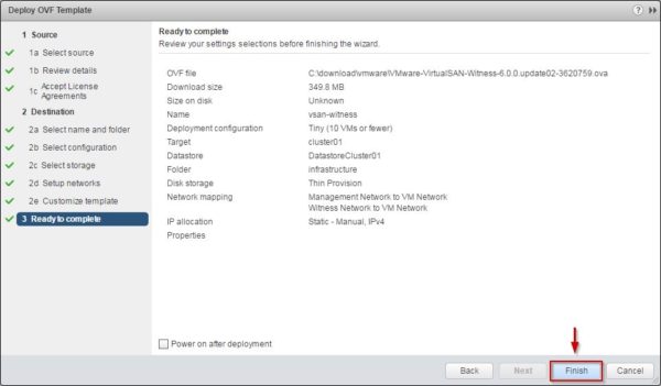
Access VMware vSphere Web Client and right click the configured cluster. Select Deploy OVF Template option to start the wizard.
Click Browse and select the Witness appliance .ova file downloaded from VMware website. Click Next.
Click Next to continue.
Accept the EULA then click Next.
Enter the appliance Name and select the desired folder. Click Next to continue.
Depending on the size of your network, select the Configuration that best fits your environment.
Select the disk format and the location to store the VA then click Next. There is no requirement to use a flash device in the appliance.
Static IPs should be used in the VA network configuration. Click Next.
Set the Password for the root account then click Next.
Click Finish to start the deployment.
Configure the Management Network
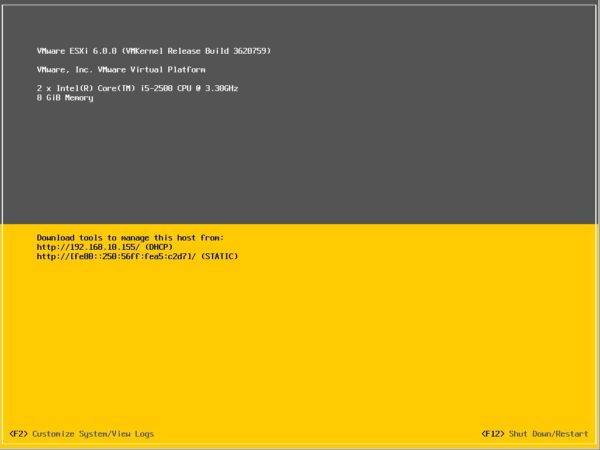
Power on the VA and access the console.
Insert the root credentials to access the configuration.
Assign a static IP to the Management Network and apply the configuration.
Add Witness VA to vCenter Server
Once the Witness virtual appliance has been deployed e configured with a static IP, it should be added to vCenter as an ESXi host. Right click the Datacenter and select Add Host option.
Type the Host name or IP address and click Next.
Enter the credentials to connect to the host and click Next.
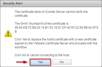
Click Yes to accept the certificate.
Click Next to continue.
The Witness appliance comes with per-configured license so already installed licenses are not consumed.
If you need to restrict the access to the appliance, enable the Lockdown mode. Leave default value Disabled and click Next.
Specify the VM location and click Next.
Click Finish to save the configuration.
The Witness VA has been added to the Datacenter. Note that the Witness appliance is in blue to distinguish it from other ESXi hosts in the cluster. In addition there is a No datastores have been configured warning on the host because the nested ESXi host doesn't have any VMFS datastores configured. This warning can be ignored.
Configure the VSAN network
From the VMware vSphere Web Client select the Witness VA and access the Manage > Networking > Virtual switches tab. By default the appliance comes with two virtual standard switches with configured uplinks:
- vSwitch0 - used for the management network
- witnessSwitch - used for the VSAN network
Since the VSAN network on the witness site needs to communicate to the VSAN network, edit the witnessSwitch and add a VLAN for the VSAN network.
Set the correct VLAN ID used for the VSAN communication and click OK.
In the VMKernel adapters tab, highlight the witnessPg portgroup and click the pen icon to edit the parameters. Don't remove this port group because it is configured so that the virtual machine network adapters MAC addresses matches the vmnic MAC address of the nested ESXi host.
In the Port properties you find a VMKernel port already configured with the Virtual SAN traffic option enabled.
In the IPv4 settings you can specify a static IP address. Click OK to save the configuration.
In part 2 the configuration will be completed with the creation of the Fault Domains and the VSAN cluster setup.


